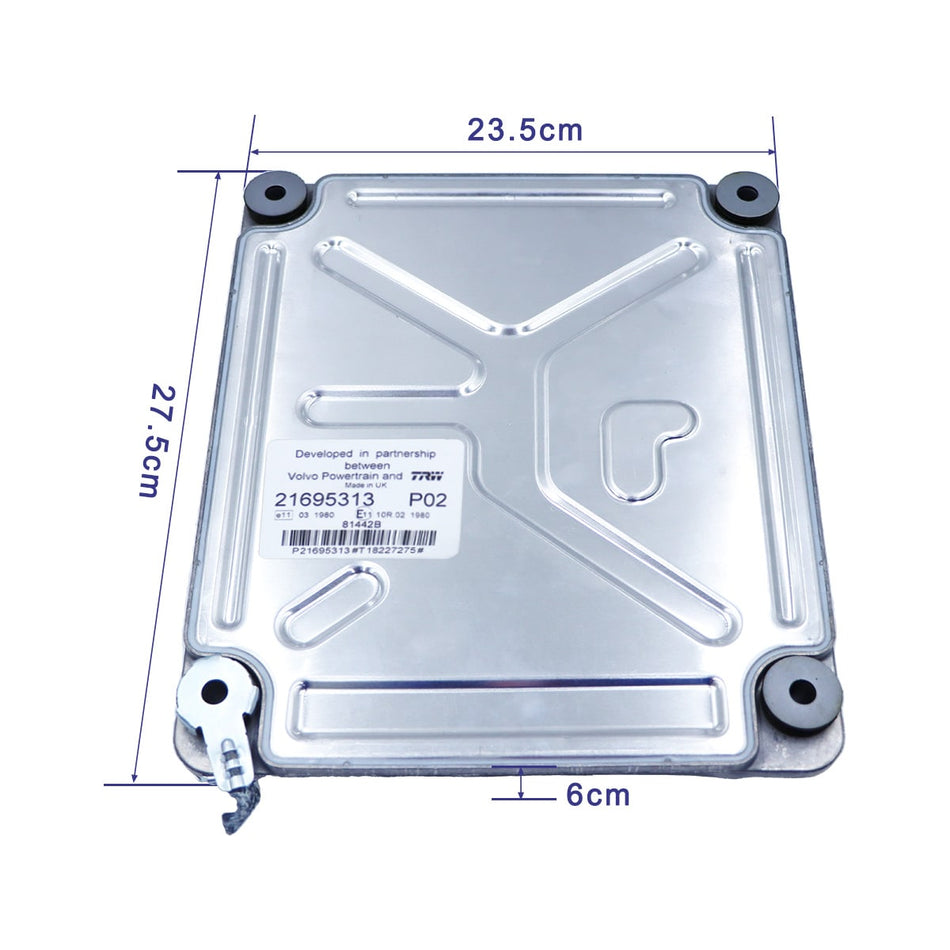
With the maturity of the technology used in the field of machinery, the original control system for excavator repair is gradually being replaced by the PC system. In everyday use, the number of vehicles represented by PC control is increasing. Due to the lack of control, the intermediate relay is eliminated, only the switch control is used, the circuit is simple, and the environment is capable of adapting to many other advantages. The comparison of the control system shows a number of superior performance. However, with the prolonged use of the machine, the failure of the PC system has gradually emerged, making the machine unable to work in good condition. Due to the limited knowledge of the PC system by the mechanical operators or maintenance personnel, the number of machines in the station is increasing, resulting in a decline in the integrity rate and affecting normal production. For example, replacing the entire integrated board is not only costly but also has a long purchase period. This requires finding a way to solve the problems in the PC system. 1 Failure causes The failure of the PC system is mainly caused by external conditions.
The reasons are as follows:
1.1 Open circuit failure
(1) Parts are broken due to fusing: such as fuses, fuses, bulbs, thermal contacts, transistors (safeners, converters, controllers).
(2) Open circuits caused by cables and coils: such as engines, generators, relays, buzzers, solenoid valves, etc.
1.2 Connection failure (indicator indicates instability or infinity) Excavator repair
(1) Corrosion-induced failure: such as battery end point, connector Outside to water.
(2) Faults caused by surface connections: such as switches, relays, connectors, and various ohmic forms.
1.3 Short circuit fault
(1) Short circuit fault caused by broken wire.
(2) Internal short circuit of components, such as internal short circuit of coils, switches and relays.
(3) Static electricity caused by contact with other machinery causes malfunction.
2 Analysis and solution steps The following is an example of the analysis and solution steps of the electromagnetic system failure of the rotary brake brake of the Komatsu PC100 excavator. The control principle is shown in Figure 1.
Figure 1 Control schematic diagram
(1) Observe the indicator light on the meter. If the rotary brake solenoid valve light is on, it proves to be faulty.
(2) Check the electrical components on the periphery of the control board. The search procedure is shown in Figure 2.
Figure 2 search step (3) to check the control panel, the measurement method is as follows:
1 start the engine;
2 switch outside the normal position;
3 insert T-connector;
4 measure the voltage between the control board CN-13 and 6 points (table 1) If it is not between 20-30V, it will prove that the components of the control board are faulty. Table 1 control board CN-1 sequence signal name output input 1 battery output output 2LS cutoff solenoid valve output 3 rotary hold brake solenoid valve output 4NC–5NC–6GUD input 7 power supply (+24) input 8LS distribution solenoid valve output 9 Car selector solenoid valve output 102 level relay valve output 11NCGND input 13 power supply (+24) input (4) Remove the control board and test the components on the control board one by one with the tester (Huoneng online maintenance tester).
The rough test is tested with the quick test method, and the component will be separated and listed, indicating the fault range. Repair the excavator to connect the board and the tester according to the regulations, select the USER (user-defined library) device library, and then input the component code. If the component U1 fails the test, check the IC in U1. There are often many ICs on a board to be tested. It is like finding a needle in a haystack. If you don’t know which IC on the board may have a problem, you need to “return the test”. After testing, only the conclusion of whether the IC passes or not can be obtained without providing any information such as fault diagnosis and waveform analysis. In this way, a large number of devices on the board can be screened, a good IC can be picked out, the scope of the faulty IC can be narrowed, and a further “diagnostic test” can be made for screening out the IC that cannot pass. 2 Detailed measurement of the “bad zone” chip to do a more in-depth analysis, inspection work, to falsely save the truth, to locate the real point of failure. When “fine measurement” diagnostic test.


